Wednesday, October 26, 2011

160m/75m/40m Fan Dipole

After having a problem with the 75m bazooka I decided to put up a fan dipole for the winter.  The bazooka, which was made of two pieces of RG-213 soldered in the middle, failed this fall.  I believe the solder joint came apart inside the conduit body that it was epoxied into.  I was looking at putting up a remote coax switch and running multiple bazookas.  This gives me multiple bands on one feedline without the switch.  It is resonant on 160m, 75m, and 40m.  It also happens to work on several other bands as well.  I can move quite a bit on 75 and 160, very much to my surprise.

Center spreaders, support, and feed insulator.

The next two photos are of the wire legs, fiberglass rod spreaders, and strain insulators on the ends.
  I cut down driveway reflectors to use the rods as the spreaders, they seem to work well so far.


Sep. 2016 Update:

After 5 years of service, I have a failure.  Well, sort of.  One of the dogs chewed a guy rope off and my daughter got into the wire with the tractor while mowing.  This caused some of the fiberglass rods to split.  The center insulators took the abuse, but I will have to take the entire antenna down to measure and replace the elements that got chopped and wound up in the tractor mower.

Tuesday, September 27, 2011

Tuesday, May 10, 2011

WSPR - Digital Mode or Propogation Beacon ?

I heard some HAM's talking about a mode they called "whisper".  I was curious so started digging around the web and found the related site, downloaded the software and started listening.

WSPR, pronounced "whisper", seems to be a beacon system.  Although reading on the site some users don't want to call it that because of legal ramification, but what else do you call a system that sends a stations call, grid locator and power level on a very narrow, low power radio signal at random time intervals?

If it is not a beacon what is it?  The stations do not communicate on the air, the software simply receives the signals and decodes them and automatically posts them to the web.  You do not call CQ and have a conversation or echange information on air.  I say if it is not a beacon, it is a one way transmission.

The site, http://wsprnet.org describes it as follows;  "The Weak Signal Propagation Reporter Network is a group of amateur radio operators using K1JT's MEPT_JT digital mode to probe radio frequency propagation conditions using very low power (QRP/QRPp) transmissions. The software is open source, and the data collected are available to the public through this site."

Here is the screenshot of stations I heard on 20m with the bazooka at 20 feet on the morning of May 10, 2011.


You can visit the live map at http://wsprnet.org/drupal/wsprnet/map.

Friday, May 6, 2011

NVIS-what antenna to use?

I have been using an NVIS antenna over the winter with good results.  I have been able to make contacts with another station when other types of propagation would not work.

Several articles have been written on the several styles of antenna that may be used for NVIS and the operating style that must be used for NVIS operation.  NVIS is not for DX’ing it is a method used to get regional coverage of an area.  It is a very attractive method for emergency management and state net use.  It also works well to get HF communication between areas on either side of a mountain or to cover a mountainous area where line of sight is not possible.

For those who are not familiar with NVIS, the idea is to get as much of your radiated signal as close to straight up as possible.  This causes the F2 layer to “scatter” your signal back down.  I liken it to shining a flashlight on a ceiling of a very dark room.  The light is directed upwards, yet the light is scattered by the ceiling and illuminates the floor.  If this is done in a large room and the light is pointed straight up, the area around the flashlight will be brightest with the intensity dropping as you move away from the flashlight.  The same is true for the RF energy reflected by the F2 layer.

The nature of the F2 layer is such that not all frequencies will be reflected.  This is determined by the foF2 or the cutoff frequency of the F2 layer.  This is determined by the free electron density in the F2 layer.  An ionosound that sends pulses of RF up and measures the reflected RF samples the F2 layer and helps determine what wavelengths will be usable for NVIS.  The other layer that determines the feasibility of NVIS operation is the D layer.  During any HF operation the RF signal must make two trips through this layer.  For signals at lower angles the RF passes through more of the D layer and is therefore subject to more absorption.  The NVIS signal takes a shorter path because it is traveling at nearly a right angle to the layer and is not subject to absorption for as long a time as the lower angle wave.

As the foF2 changes, the stations involved with NVIS must change bands to maintain communications.  In the ionospheric map below you can see most of the US should be able to use a signal at 7 MHz. for NVIS.  Yet, as you look south and west of the US you see that there is an area that supports NVIS as high as 12 MHz and in the South Atlantic there is a large area that supports NVIS at no higher than 2 MHz.  Bands must be selected to match the current conditions.  All stations in a regional network should have predetermined frequencies to change to as ionospheric conditions change.  The idea that stations can use 40m during the day and 75m at night does not always work.  There may be several days or even a month or two that the higher frequencies will not support NVIS operation.


Below is the model of the 40m NVIS antenna that I used.  It is at a height of 7 feet over three reflectors.  The height is 5.4% of a wavelength and can be scaled for other bands.  The reflectors are spaced at about 4.62%.  In the model below, wire 1 is the dipole and wires 2, 3, & 4 are the reflectors.  This also shows the elevation plot of the system.  The reflector spacing is not all that critical, it is there to minimize ground losses and direct the RF energy upward.


40m NVIS


You can see in the data below that this antenna exhibits a maximum gain of 3.89dBi @ 90 degrees and relatively small gain at the lower angles.  This is what we want for NVIS.


Elevation Plot @ 7'

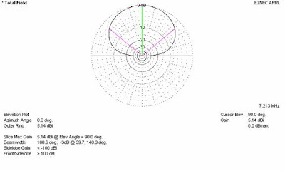
 Next the antenna modeled at 10 feet.  The antenna now exhibits 5.14 dBi at 90 degrees, in a vertical direction, but we now see greater gain from the sides.  This is not a desired affect for NVIS.  The lower angle gain brings in unwanted signals, those most likely from further away than desired for this type of operation and increases noise.


Elevation Plot @ 10'

So, what if we wanted to lower the antenna below 7 feet?

Here is a model at 4 feet above the reflectors.  We see the ground losses are now having an affect on total gain for the antenna.  The 90 degree gain is down to 1.38 dBi, while the pattern is nearly the same the power is now lost into the earth under the antenna.


Elevation Plot @ 4'

One idea I have seen and read about is placing the antenna very close to the ground, like 6 inches off the ground without a reflector wire.  The ground losses are extremely high in such a system.

Elevation Plot @ 6 inches w/o reflector
I modeled the antenna at different heights:

Height (Ft.)
Beamwidth
Gain at 90 Degrees (dBi)
10
100.6
5.14
9
100.2
4.81
8
99.6
4.4
7
99.2
3.89
6
98.8
3.26
5
98.6
2.45
4
98.4
1.38

As the antenna is raised the gain comes up, but the beamwidth also broadens.  As the antenna is lowered, the beamwidth narrows, but the gain is decreased due to ground losses.

What about a regular dipole at ¼ wave height?

1/2 wave dipole @ 1/4 wave height
As you can see the most power is radiated at low angles and little in the upward direction necessary for NVIS.

So it seems the falt top antenna over three reflectors at a height of around 7 feet is ideal as it shapes the pattern in the desired way without excessive ground loss, all while keeping the low angle gain to a minimum.

Saturday, April 30, 2011

40m Double Bazooka build.

I just built another bazooka, this one for 40m.  I used the Carol rg-6 and the same method of build I used before with one exception;  this time I used 1/2" cpvc with caps on it to create a tube to enclose the shorting point.  I drilled a hole just large enough for the mixing tip on the epoxy to fit and "injected" the epoxy into the tube.  So far it seems to be a strong joint on the 40m antenna.  I had it in the air last night and most of this morning with winds gusting to around 20mph.

The bandwidth on this antenna has exceeded my expectations.  I have the entire band below 2:1.  This antenna is actually resonant toward the low end of the band so it is hard to get an accurate 1.5:1 bandwidth, unless you are willing to TX out of the amateur spectrum.  (I am not.)

I believe if I trimmed the ends it would put the entire band below 1.5:1.  This antenna is slated to go to WB8CHE so I left the antenna as is so that he could trim it to his preference. I have been using the antenna to make a few contacts and test it out before mailing it to Russ.  I have went from the bottom of the SSB segment to the top without the use of a tuner and get full output from my Yaesu ft-450AT.

Most of the antenna on the 21' pole.  I have the antenna pretty tight just to make sure it will hold together.
The unpainted conduit body at the feed point.
The epoxy filled tube over the shorting point
(Kind of looks like a caterpillar!)
Close up of the epoxy filled cpvc tube over the shorting point.
My method of attaching a rope to the end.
The complete antenna rolled up and ready to go.

 The ends of the antenna are left raw.  During installation the SWR gets checked and the ends can be trimmed to raise the resonant frequency of the antenna.  This antenna is a bit long so that it is resonant more toward the bottom of the band.  This allows the antenna to be tuned for the particular installation.  (Better to trim than figure out how to add!)  After it is tuned, the ends should be sealed with epoxy, or silicone sealant would also work.

Monday, April 25, 2011

10m Bazooka

I am working on some new ideas for building the bazooka antenna.  This one is built with cheap carol RG-6.  This coax has a single aluminum shield without the waterproofing glue so it is easier to work with than the quad shield stuff.  I purchased a 250' spool at Menard's for $30.

I like the conduit bodies for the center but the weak link is the shorting points on each leg.   I am using epoxy and heat shrink on this antenna and yet I think it may not be enough.  If this joint fails the thought occurred to me to use a piece of PVC pipe over the shorting point and fill it with epoxy.  The down fall of this would be the added cost in materials and more epoxy.

This is the center made from a conduit body with a chassis connector installed and a stainless eye bolt, washers, and nuts for supporting the antenna.  The RG-6 has an aluminum shield so I have used crimp eyelets to make the connections to the coaxial connector.  The eyelet going to the center is soldered in place.


Here I have the body filled with 3 oz of 5 minute epoxy, this strengthens the antenna and adds weather resistance.

Here I have one end of the coax stripped back ready for the shield to be twisted around the center conductor and crimped on.

I used a piece of masking tape to mark where the end of the heat shrink tubing needed to be.

I purchased a smaller tube of epoxy with the mixing tip so I could "inject" epoxy under the heat shrink and around the crimp connector that is creating the shorting point.

This is the above connection after "injecting" the epoxy and shrinking the tubing.

This is the center after the epoxy is set and a coat of paint applied.
I wrap the connector with masking tape to keep the paint off the threads.


I put this antenna up on my 21 foot telephone pole to test it and it has 1.5:1 SWR or lower across the entire band.  The shorting points seem to be solid. (I put plenty of tension on it with the ropes on the ends.)  Although the joints seemed strong enough, I am going to use a sleeve and fill that with epoxy to seal and strengthen the next one I build, most likely for 40m or 20m.

As a side note, the 75m bazooka made with RG-213 is still going strong!

Wednesday, April 20, 2011

Saturday, April 16, 2011

The "New" Station Rig

I haven't got around to posting anything about the new rig.  I replaced the FT-767GX with a Yaesu FT-450AT.


The speaker that looks as if it came with the rig is an old center channel speaker from a Sony surround sound system.  Maybe Yaesu should get with Sony, of course that would make it $100 or more.

As you can see, I use Ham Radio Deluxe to control the rig.  Some of the features are not supported but I did write macros that makes them functional.  The menu settings are better accessed by HRD than via the radio and the dimmer, mic gain, volume, DSP, IF shift, meter selection, squelch, RF power, RF gain, keyer speed, QSK delay, VOX delay, and Vox gain are all able to be set on sliders in the software.  Even the software from Yaesu works well, almost like using the rig directly, but is easier to get at menu settings than via the rig.

I am using a serial to USB converter and both programs work great with it.  I have also played with this rig on echolink and it seems to work well.

This is a compact rig, rather small VFO knob, but the buttons are not to tough to get to.  One thing this rig doesn't have, and I don't know why, is an automatic notch filter.  This could have been put in, after all it already has DSP, so why no auto notch is beyond me.  I have good reports on air with it, although I dislike some features or lack of.  The mic gain control is a funny thing, it has three settings instead of a variable control.  I have to run the mic gain on low for SSB and HI for AM.  I checked into the AM Forum on 3.870 and the AM guys liked the audio once I moved to the HI setting on the mic gain.  This is my first "modern" Yaesu since the FT-767 so I was a bit confused by the "IPO".  This is what Yaesu calls their preamp.  In the off position the input amp is operational and in the ON position the input amp is bypassed.  It seemed a bit backward to me after using other HF rigs in the past.  I just think of it as a preamp bypass and my mind keeps it straight.

The DSP has the usual Yaesu features, contour, manual notch, DNR, and width.  All of these do their job well and rather smooth to.

The display is nice, I like the large frequency display and the subtle blue against black is easy on my eyes.  It has a five step dimmer, from off to bright, and an adjustable contrast, so one can adjust to their taste.  The buttons are black with red lettering.  This was an odd color scheme that doesn't contrast well, I would not like it for mobile use, but with all the memory channels would make use of the buttons almost unnecessary.

Speaking of mobile use, I do think this would make an excellent mobile.  It has many memory channels and keeps about every setting imaginable in the memory, DSP, ATT, IPO, and many more.  It's compact size would fit well in a pickup, but most modern cars would be hard pressed to find room for it.

The built in tuner is quick, quiet, and fast.  I was very pleased the first time I hit the tuner and watched it do it's thing.  It also has a warning beep and prevents TX when a match can not be found.

The rig puts out right at 100w on all bands and absolutely does not get warm.  Just take a look at the fan in the photo's above.  I know, that must be loud!  Nope, you barely even hear it.

All in all, the rig is a good performer, but if you are used to a big rig with a large VFO knob you will find it odd to get used to.

Sunday, February 6, 2011

Update on the Bazooka Antennas

The 75m bazooka got its first ice load test recently.  We had a winter storm that accumulated approximately 1/2" of ice on the antenna.  I had no failures of the antenna.  I did have to lower it, that's when I took the photos, and shake the ice off to get the SWR down.  I had not expected the icing to effect the antenna as bad as it did.  The ice raised the SWR to 2:1 and up across the bandwidth of the antenna that was resonant before.  After I removed the ice and raised the antenna back to it's proper place, it was back to business as usual on 75m.

The prototype I had up as NVIS on 40m has a problem.  I think the strain from the ice has caused one of the shorting points, or the feed point to pull apart.  The SWR is so high the antenna is unusable.  The 40m antenna had not been epoxy sealed so it is likely the feed point.